Free Canada* Shipping on Orders $500 or More! Find A Dealer.
This page is being developed at the moment, still in beta mode.
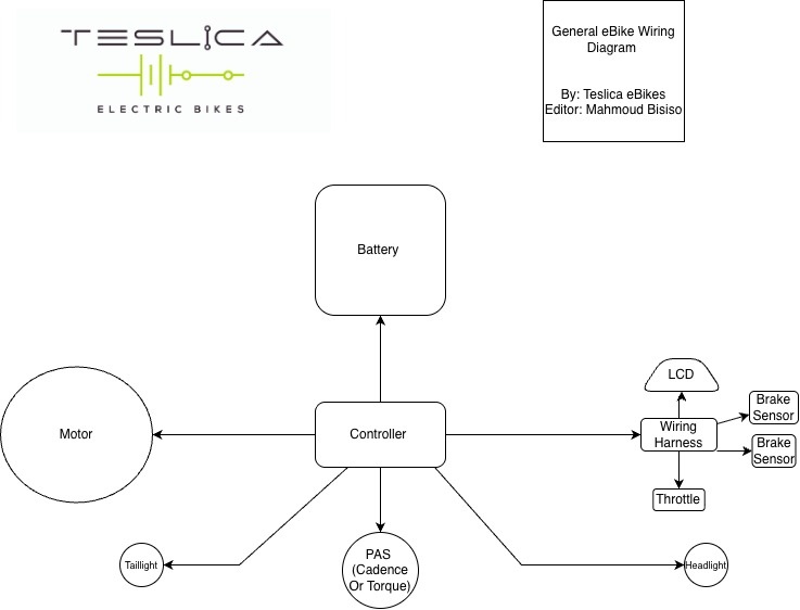
| Wire | Role | Expected Voltage (measured to ground) |
| Red | Power | Just under 5 V |
| Ground (GND) | Ground | 0 V |
| Small Yellow | Yellow Hall Sensor | Toggle between 0 V and 5 V as you engage motor or pedal backwards |
| Small Blue | Blue Hall Sensor | Toggle between 0 V and 5 V as you engage motor or pedal backwards |
| Small Green | Green Hall Sensor | Toggle between 0 V and 5 V as you engage motor or pedal backwards |
| Thicker Yellow | Yellow Phase Wire | No need to measure voltage |
| Thicker Blue |
Yellow Blue Wire |
No need to measure voltage |
| Thicker Green | Yellow Green Wire | No need to measure voltage |
| White wire | Speed hall sensor | Toggle between 0 V and 5 V as you engage motor or pedal backwards |
Failure indicators:
Hall sensor failure symptoms on ebike:
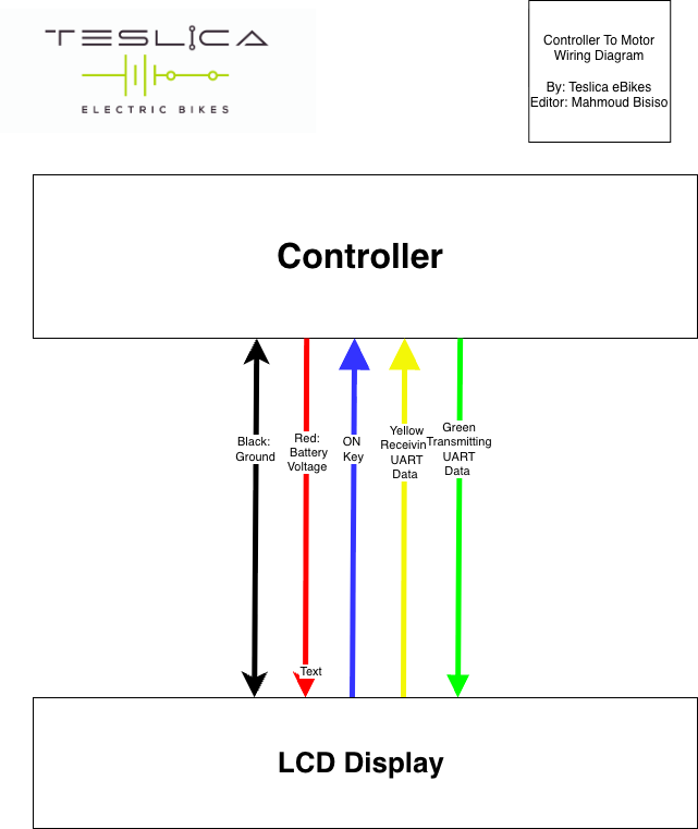
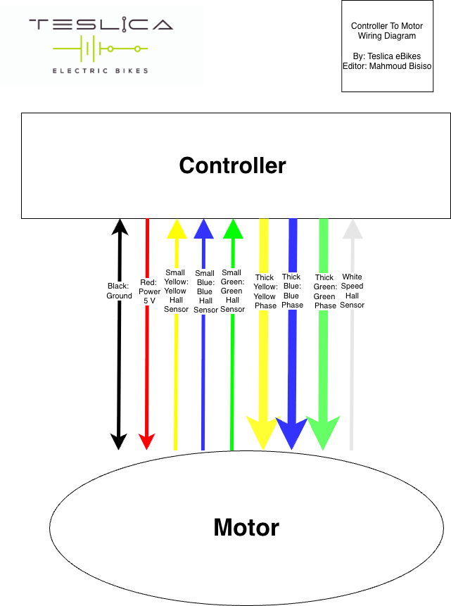
| Wire | Role | Expected Voltage (measured to ground) |
| Red | Battery Power | Same voltage as battery (yes, it can be more than 60 V) |
| Ground (GND) | Ground | 0 V |
| Blue | ON Key: Tells the controller when LCD is on | 0 V when off, Almost same voltage as battery when on (yes, it can be more than 60 V) |
| Yellow | Receiving UART Communication Data | UART (alternating 0 - 5V communication) |
| Green | Transmitting UART Communication Data | UART (alternating 0 - 5V communication) |
Failure indicators:
Notes:
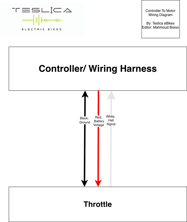
| Wire | Role | Expected Voltage (measured to ground) |
| Red | Power | 5 V |
| Ground (GND) | Ground | 0 V |
| White | Throttle hall signal |
When throttle is off: around 0.6-0.8 V When throttle is on: around 4.2V |
You cart is currently empty